John
Doran's
Technical Hobby
Web Site
Technical Hobby
Web Site
Links
|
John
Doran's
Technical Hobby Web Site |
Home Links |
| Dual-Discharge Current Regulator Page.
Click
on pictures to get larger/higher quality images. |
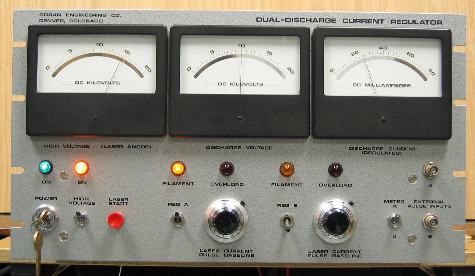
| This device functions as part of
a gas laser power supply, taking the place of the ballast
resistance. It's a real, active constant-current source whose
dynamic impedance is essentially infinite; yielding excellent stability
and fine control over a broad range. There are two independent current regulators in the chassis, permitting the simultaneous operation of two lasers or of a single laser having three electrodes (one anode and two cathodes). For each regulator section, there is a front-panel control and an external signal input; the actual current is then the "sum" of the set value and the external input. The unit can accept up to 20 kV on its DC input, and can regulate the current in loads dropping 18 kV or more. |
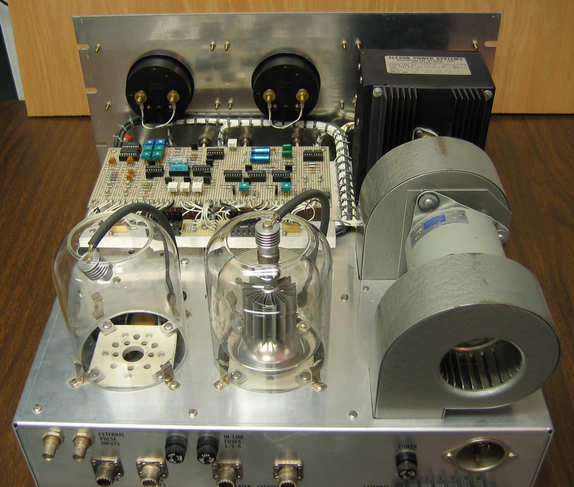 |
« This photo shows the top of the chassis. The big power triodes, with their sockets and chimneys, are on the lower left (I have removed one tube so that the socket and its mounting scheme may be more easily seen). |
 |
« This is a closer look at the electronics board. The regulator FETs and their source resistors are mounted on the aluminum rail in the foreground. |
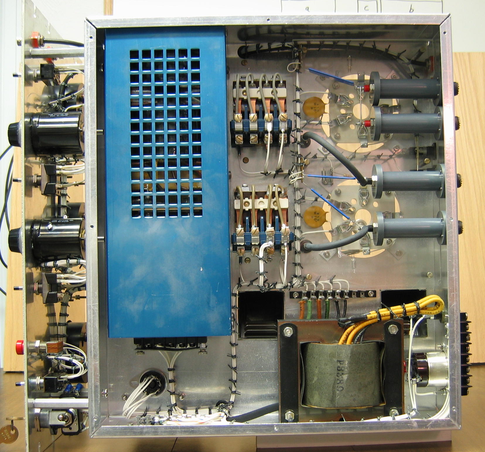 |
« Here is a view under the chassis. The blue box is the + 24V power supply, and the big transformer supplies power for the tube filaments. The wiring around the tube sockets may be seen through the acrylic insulating sheet at the upper right. |
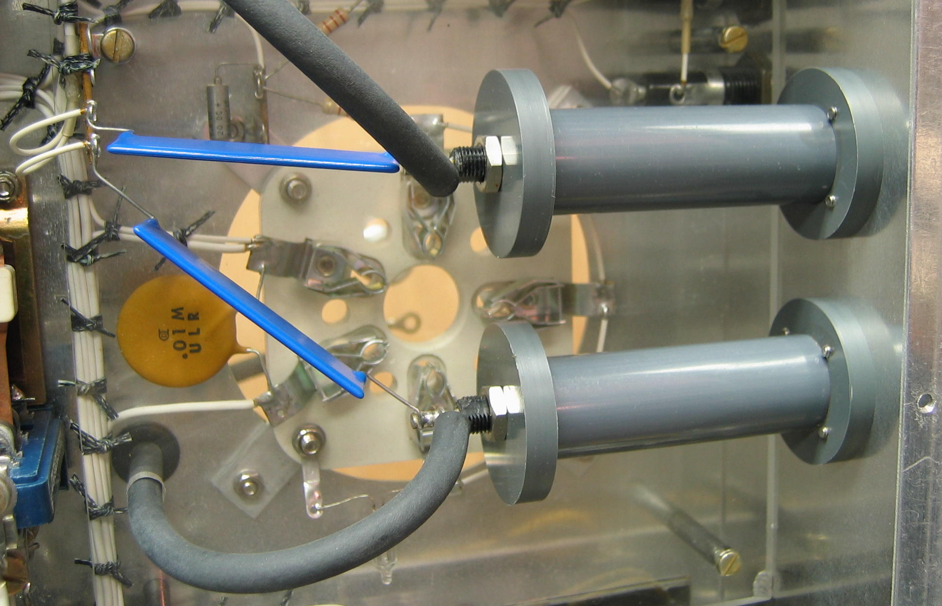 |
« This is a close-up of a pair of my home-made high voltage connectors, showing how they are constructed and mounted in the chassis. Note the banana jack at the rear of each connector body. |
 |
« This photo shows how the
RG-8 coax cable is prepared for mating with the HV connectors.
RG-8 can withstand over 40 kV in high-voltage service. Note the modified SO-239 receptacle shells on the outside of the chassis. |
| Documentation for the regulator
follows. All docs are Adobe .PDF files, except where indicated. REG_SCH Schematic diagram. reg_design_notes (HTML) Design and Construction Notes. |
| Copyright TimeFracture 2004. |