John
Doran's
Technical Hobby
Web Site
Technical Hobby
Web Site
Links
|
John
Doran's
Technical Hobby Web Site |
Home Links |
| Old Time Radio Page.
Click
on pictures to get larger/higher quality images. |
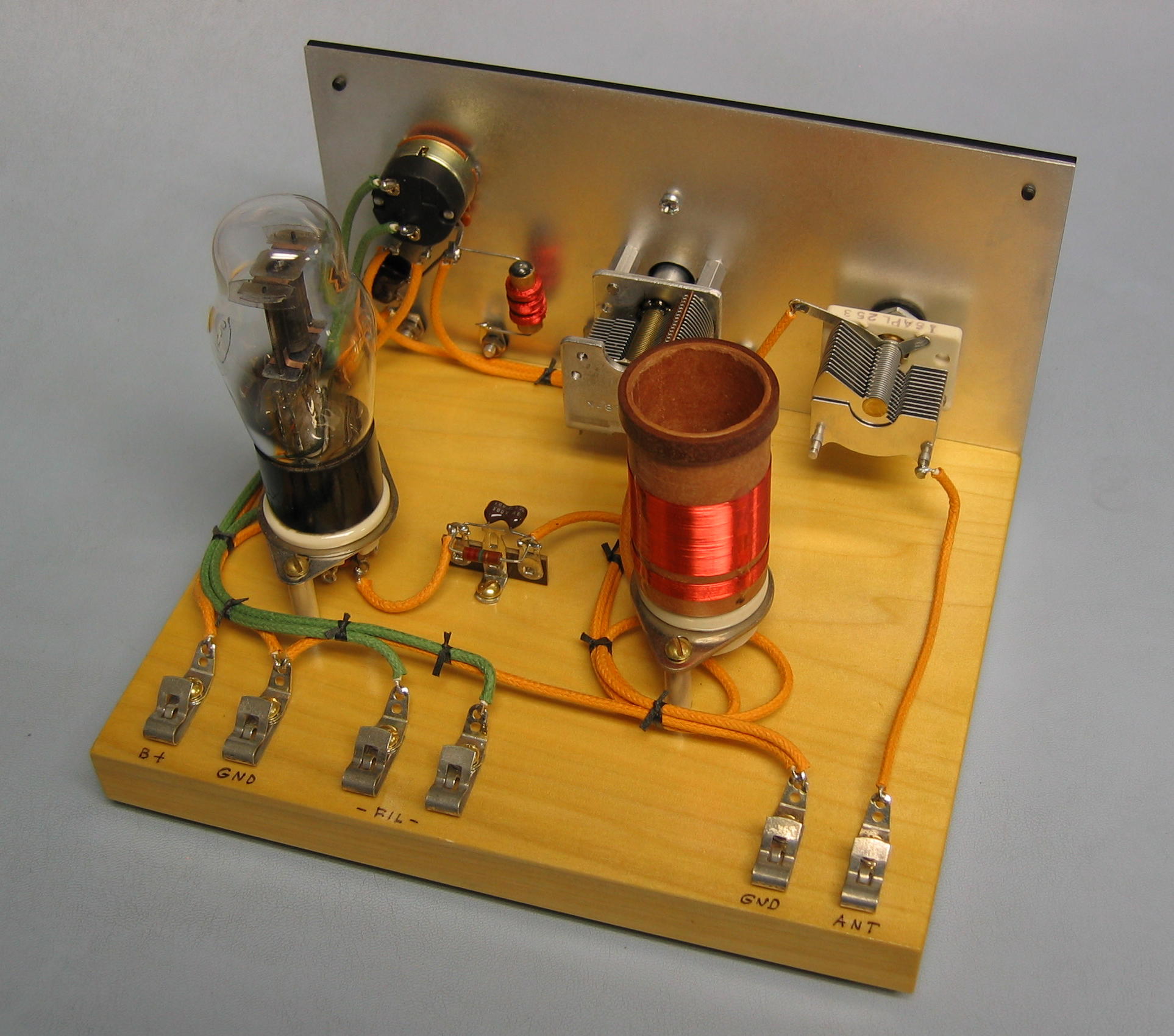
| Decades ago, while I was still
in grade school, I borrowed a book from the school library and
practically wore it to tatters reading it over and over again-- "The
Boy's First Book of Radio and Electronics," by Alfred Morgan. For some reason, I never actually built a single one of the many radio and amplifier projects that Morgan had presented in his book. I must have been more of a dreamer than a doer, way back then. Well, in June of 2003, I ran across a copy of the book in a used book store and bought it. The ensuing wave of nostalgia proved overwhelming, and before I knew it, I had ordered parts! |
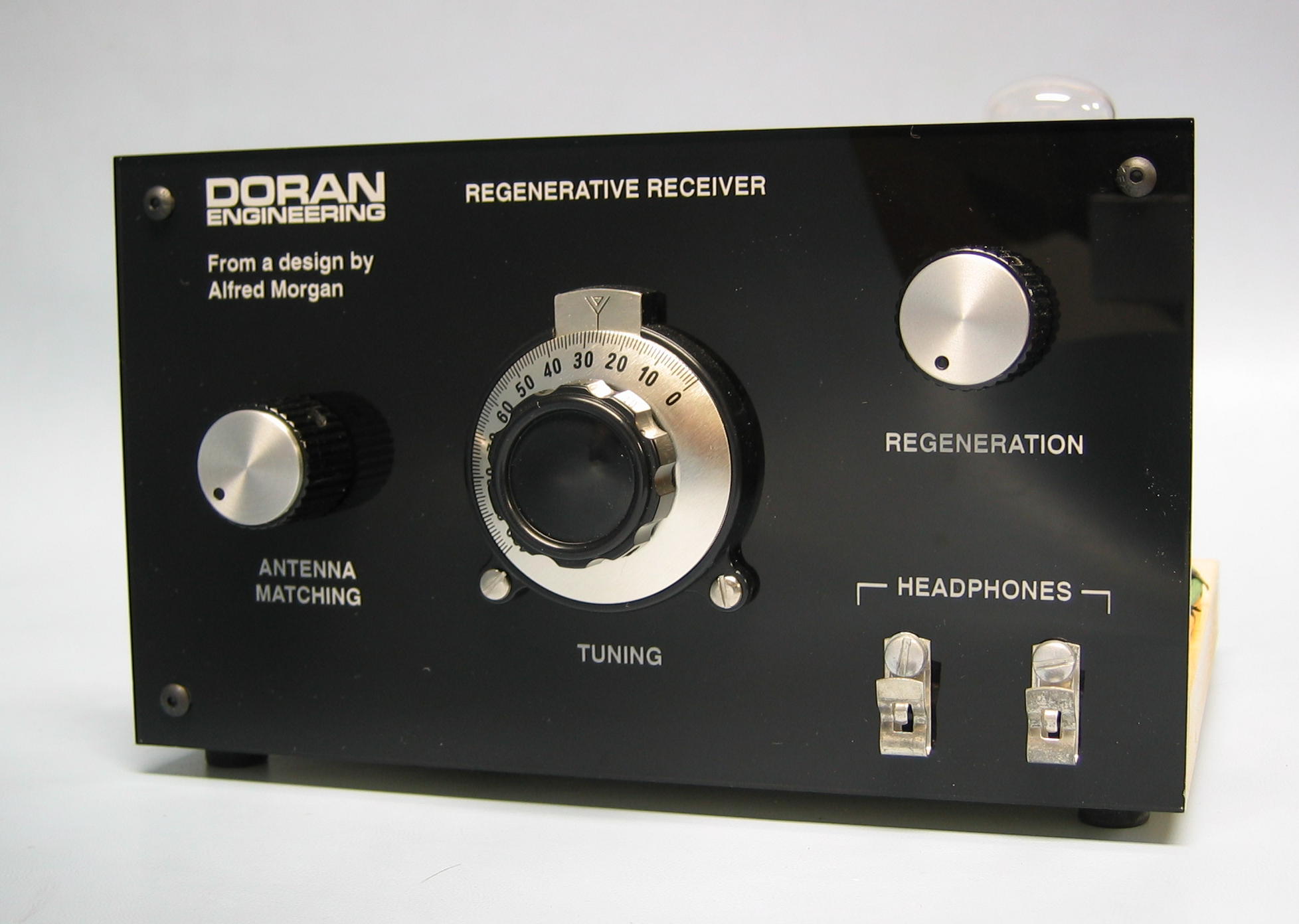 |
« Here is the receiver's
front
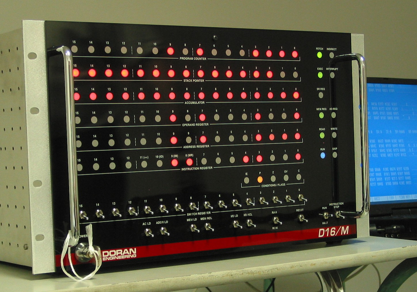
panel. I laser-engraved a piece of black-painted clear acrylic to
make it, using the same technique described in the Design and
Construction Notes for the D16/M minicomputer. |
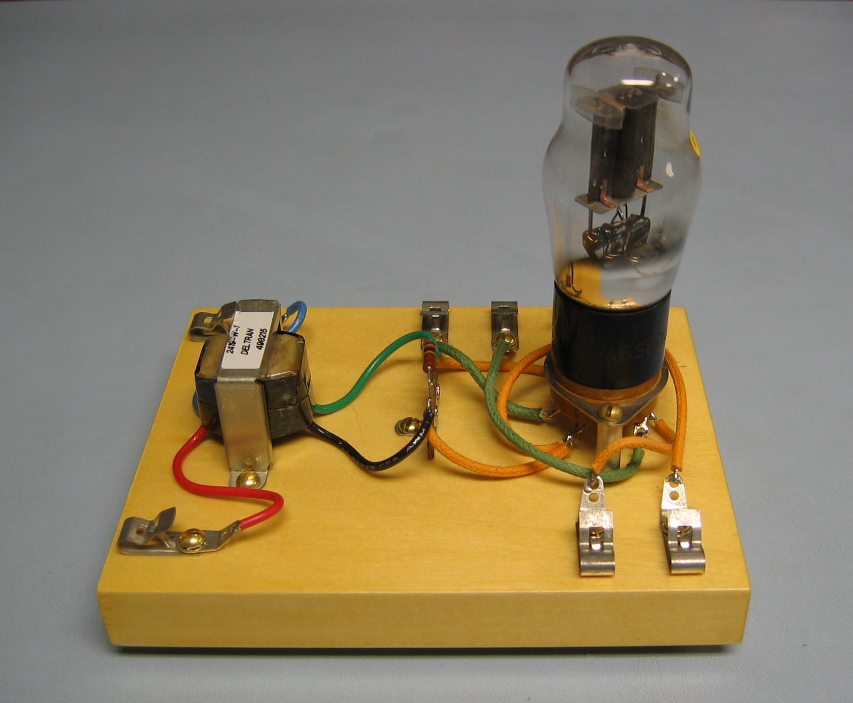 |
« This is Morgan's
transformer-coupled, one-tube audio amplifier, intended for use with
the
receiver. As in the receiver itself, I substituted an older
"Coke-bottle" envelope triode (a 6C5 G) for the miniature type 6BF6
that
Morgan had specified in the book. |
 |
« Morgan also presented
this little two-tube amplifier! I kept the 6BF6 tubes for
this one. This amp, as shown in the book, had a fatal flaw even
in the13th printing (easily fixed, though; see my Radio Notes)--making
me wonder just how many kids actually built it. |
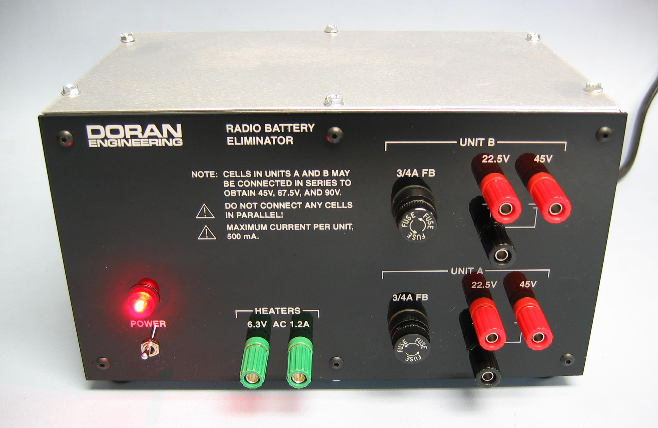 |
« Projects like
Morgan's were intended to be run on radio "B"
batteries; 22.5V, 45V, 67.5V, and 90V units were typical. You can still
buy
these batteries, but they are really expensive and last only a short
while. Why not build my line-operated "battery eliminator" power
supply instead? |
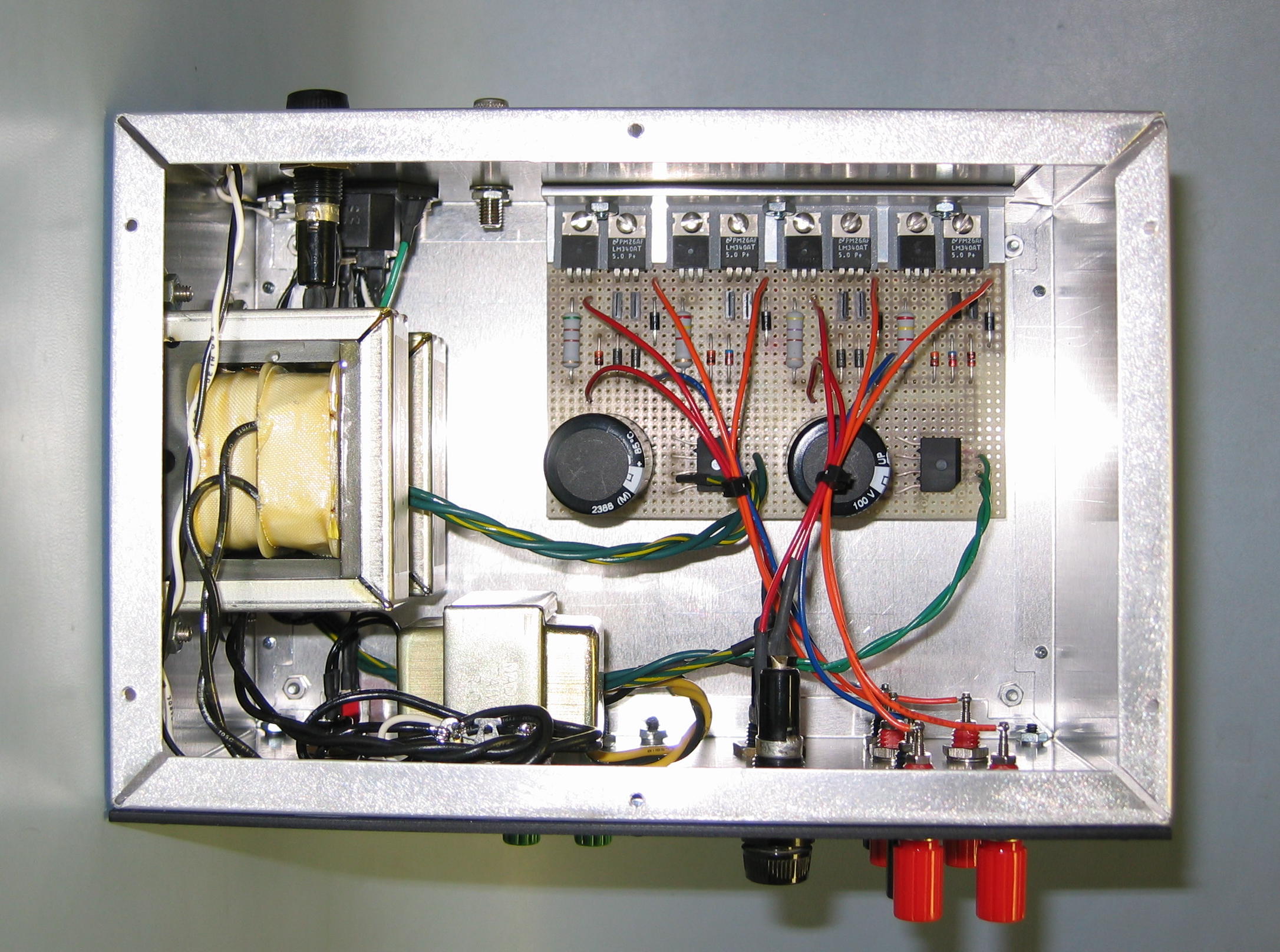 |
« Here is a look inside
the battery eliminator. It contains two independent
transformer-isolated dual-output regulated DC power supplies in one
cabinet, arranged so that they may be connected in series to get the
range of simulated battery voltages. A separate filament
transformer provides 6.3V AC for the tube heaters. |
| Documentation follows; Adobe PDF
unless otherwise stated. ELIMINATOR_SCH Schematic diagram of the battery eliminator power supply. radio_notes (HTML) Construction Notes for the radio gear and battery eliminator. |
| Copyright TimeFracture 2005-2009. |